Capitol College
Spring Semester 2000
Lab Experiment #5
Andy Buettner
Instructor: Dr. Thomas
Due:
Received: ___________________
Table Of Contents:
Section Page #
Title Page???????????? 1
Table of Contents????????? 2
Objective????????????. 3
Equipment Used?????????.. 3
Equipment used?????????.. 3
Materials used??????????. 3
Procedures???????????... 3
Part 1?????????????... 3
Part 2?????????????... 3
Results?????????????. 4
Table 1:????????????... 4
Diagram 1:???????????.. 4
Diagram 2:???????????.. 5
Table 2:????????????... 5
Table 3????????????.... 5
Table 4:????????????... 5
Table 5:?.???????????.. 6
Table 6:????????????... 6
Diagram 3:???????????.. 6
Diagram 4:???????????.. 7
Answers to Lab Questions?????. 7
Conclusions??????????... 9
Attachments??????????... 9
![]() Objective
Objective
The objective of this lab is to use a specific circuit to study a simple resistor - capacitor combination to discover how capacitors charge and discharge. Then calculate the time constant to prove that the mathematical interpretation of the circuit is correct.
![]() Equipment
Used
Equipment
Used
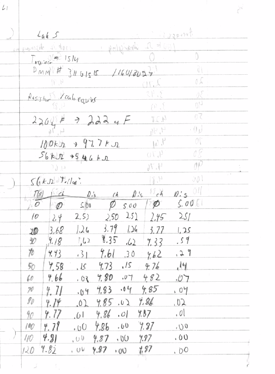
DMM #31101515, 16018027
ET - 3100 Trainer #1514
EE - 159 Lab kit
Parts used
56KW resistor
100KW resistor
220mF capacitor
![]() Procedures
Procedures
Select a 56KW resistor and a 220mF capacitor.
Measure and record their actual values.
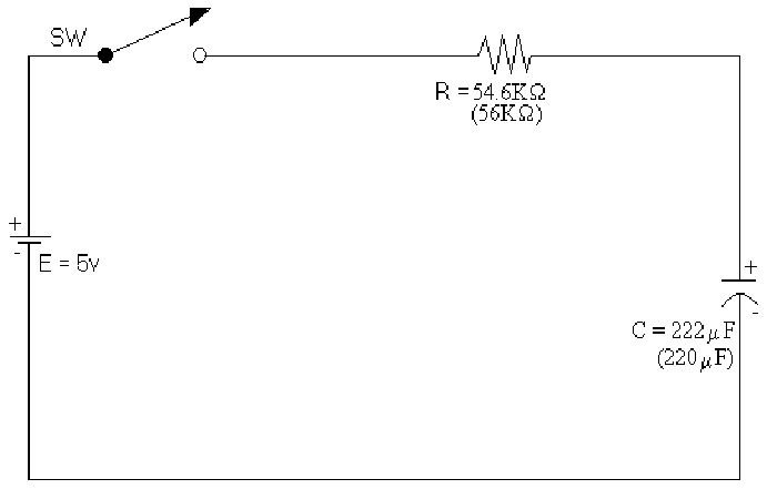
Construct the following circuit:
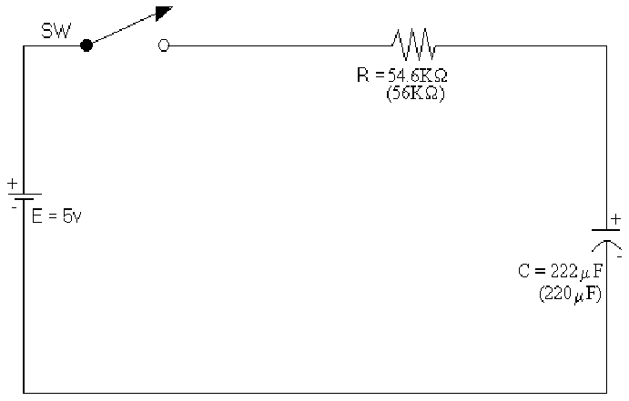
Power the Trainer to 5V.
Close the switch and record the voltage across the capacitor for two minutes at intervals of ten seconds.
Disconnect the circuit leaving the components fully charged..
Part 2: Discharging phase
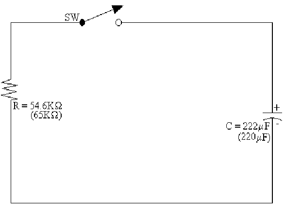
Construct the following circuit:
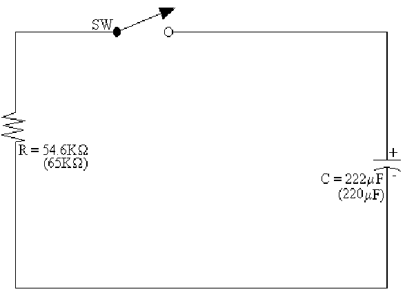
Close the switch and measure the voltage across the capacitor for two minutes at intervals of ten seconds.
![]() Repeat
this procedure 2 additional times with the 56KW
Repeat
this procedure 2 additional times with the 56KW
resistor
and 3 additional times with the 100KW
resistor.
![]()
![]() Results
Results
![]() Table
1: Resistor / Capacitor equivalent values
Table
1: Resistor / Capacitor equivalent values
|
Indicated value |
220 mF |
56KW |
100KW |
|
Actual value |
222mF |
54.6KW |
97.7KW |
![]() Diagram
1: Schematic of Circuit 1 (Enlarged view)
Diagram
1: Schematic of Circuit 1 (Enlarged view)
![]() Diagram
2: Schematic of circuit 2 (Enlarged view)
Diagram
2: Schematic of circuit 2 (Enlarged view)
![]() Table
2: Samples for the charging process using 56KW
resistor
Table
2: Samples for the charging process using 56KW
resistor
Time:
|
Trial |
0s |
10s |
20s |
30s |
40s |
50s |
60s |
70s |
80s |
90s |
100s |
110s |
120s |
|
1 |
0v |
2.40v |
3.68v |
4.18v |
4.43v |
4.58v |
4.66v |
4.71v |
4.74v |
4.77v |
4.79v |
4.81v |
4.82v |
|
2 |
0v |
2.50v |
3.79v |
4.35v |
4.61v |
4.73v |
4.80v |
4.83v |
4.85v |
4.86v |
4.86v |
4.87v |
4.87v |
|
3 |
0v |
2.45v |
3.77v |
4.33v |
4.62v |
4.76v |
4.82v |
4.85v |
4.86v |
4.87v |
4.87v |
4.87v |
4.87v |
![]() Table
3: Samples for the discharging process using 56KW
resistor
Table
3: Samples for the discharging process using 56KW
resistor
Time:
|
Trial |
0s |
10s |
20s |
30s |
40s |
50s |
60s |
70s |
80s |
90s |
100s |
110s |
120s |
|
1 |
5.00v |
2.53v |
1.26v |
.62v |
.31v |
.15v |
.08v |
.04v |
.02v |
.01v |
.00v |
.00v |
.00v |
|
2 |
5.00v |
2.52v |
1.26v |
.62v |
.30v |
.15v |
.07v |
.04v |
.02v |
.01v |
.00v |
.00v |
.00v |
|
3 |
5.00v |
2.51v |
1.25v |
.59v |
.29v |
.14v |
.07v |
.04v |
.02v |
.01v |
.00v |
.00v |
.00v |
![]() Table
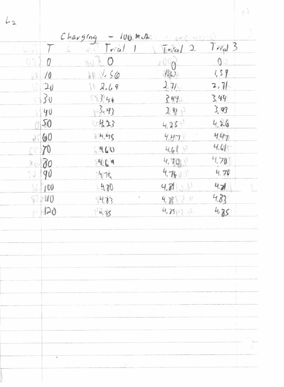
4: Samples for the charging process using 100KW
resistor
Table
4: Samples for the charging process using 100KW
resistor
Time:
|
Trial |
0s |
10s |
20s |
30s |
40s |
50s |
60s |
70s |
80s |
90s |
100s |
110s |
120s |
|
1 |
0v |
1.56v |
2.69v |
3.46v |
3.93v |
4.23v |
4.45v |
4.60v |
4.69v |
4.76v |
4.80v |
4.83v |
4.85v |
|
2 |
0v |
1.63v |
2.71v |
3.44v |
3.93v |
4.25v |
4.47v |
4.61v |
4.70v |
4.76v |
4.81v |
4.83v |
4.85v |
|
3 |
0v |
1.59v |
2.71v |
3.44v |
3.93v |
4.36v |
4.47v |
4.61v |
4.70v |
4.76v |
4.81v |
4.83v |
4.85v |
![]() Table
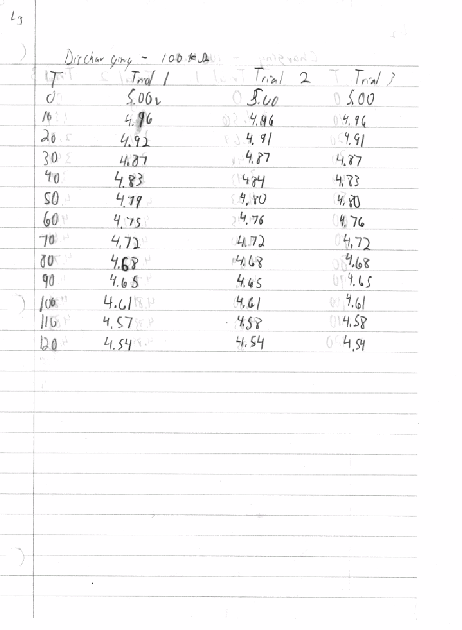
5: Samples for the discharging process using 100KW
resistor
Table
5: Samples for the discharging process using 100KW
resistor
Time:
|
Trial |
0s |
10s |
20s |
30s |
40s |
50s |
60s |
70s |
80s |
90s |
100s |
110s |
120s |
|
1 |
5.00v |
4.96v |
4.92v |
4.87v |
4.83v |
4.79v |
4.75v |
4.72v |
4.68v |
4.65v |
4.61v |
4.57v |
4.54v |
|
2 |
5.00v |
4.96v |
4.91v |
4.87v |
4.84v |
4.80v |
4.76v |
4.72v |
4.68v |
4.65v |
4.61v |
4.58v |
4.54v |
|
3 |
5.00v |
4.96v |
4.91v |
4.87v |
4.83v |
4.80v |
4.76v |
4.72v |
4.68v |
4.65v |
4.61v |
4.58v |
4.54v |
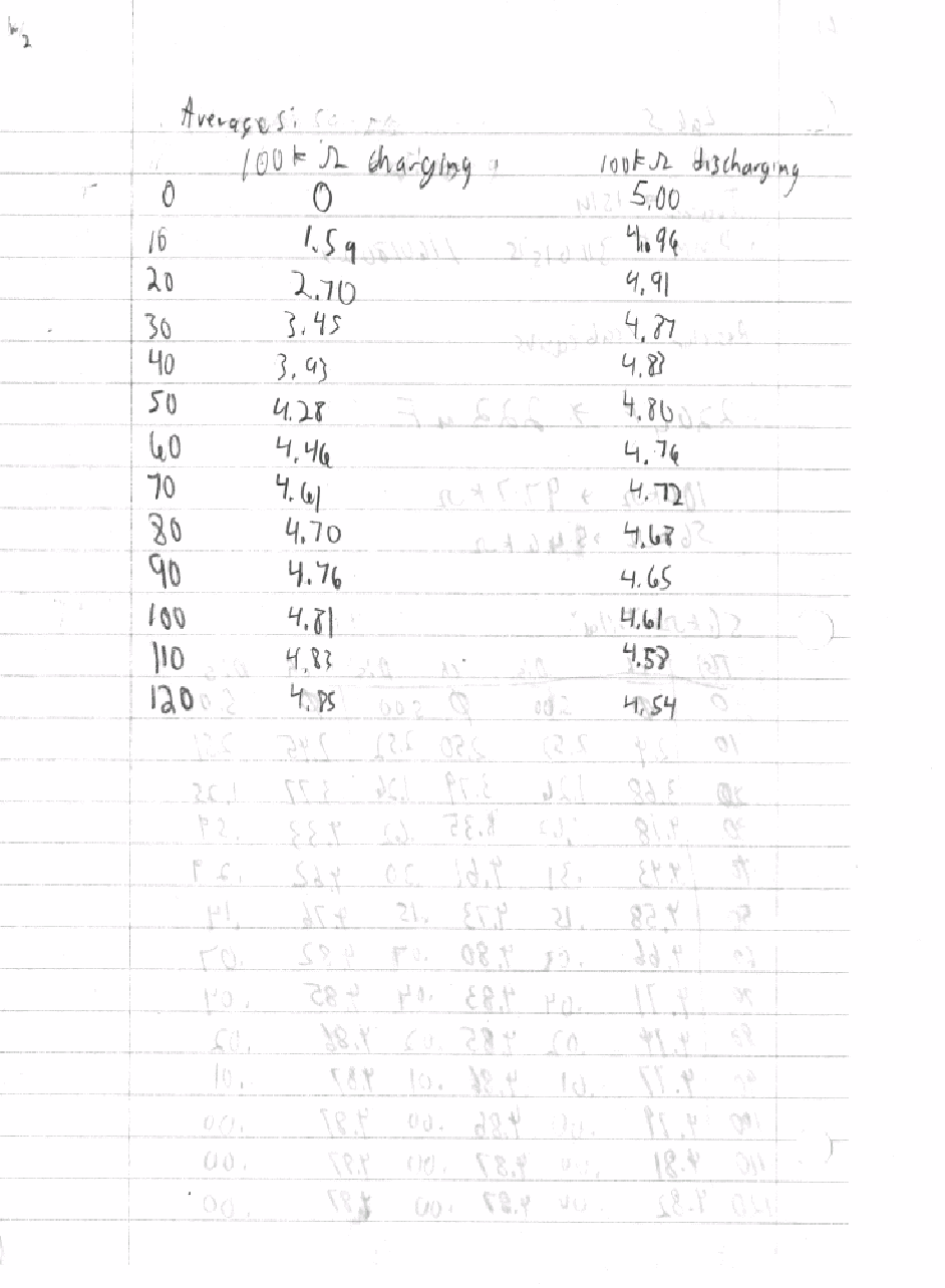
![]() Table
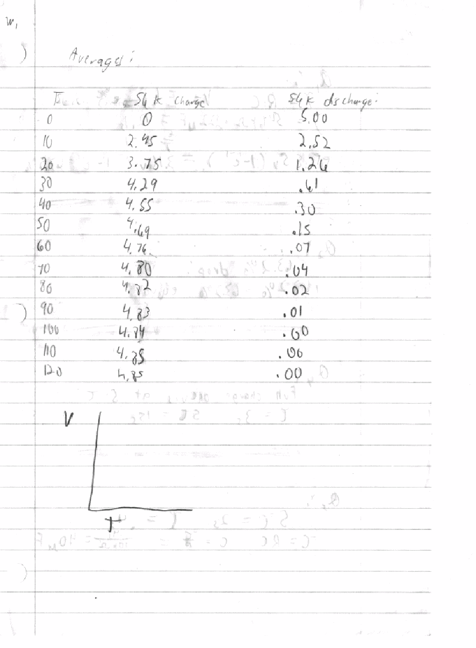
6: Table of average voltages
Table
6: Table of average voltages
Time |
56k |
100K |
56K |
100K |
|
0s |
5.00v |
5.00v |
0v |
0v |
|
10s |
2.52v |
4.96v |
2.45v |
1.59v |
|
20s |
1.26v |
4.91v |
3.75v |
2.70v |
|
30s |
.61v |
4.87v |
4.29v |
3.45v |
|
40s |
.30v |
4.83v |
4.55v |
3.93v |
|
50s |
.15v |
4.80v |
4.69v |
4.28v |
|
60s |
.07v |
4.76v |
4.76v |
4.46v |
|
70s |
.04v |
4.72v |
4.80v |
4.61v |
|
80s |
.02v |
4.68v |
4.82v |
4.70v |
|
90s |
.01v |
4.65v |
4.83v |
4.76v |
|
100s |
.00v |
4.61v |
4.84v |
4.81v |
|
110s |
.00v |
4.58v |
4.85v |
4.83v |
|
120s |
.00v |
4.54v |
4.85v |
4.85v |
![]() Diagram
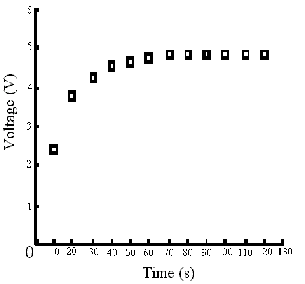
3: Graph of Voltage vs. Time for the charging phase of the 220m
F capacitor and the 56KW
resistor.
Diagram
3: Graph of Voltage vs. Time for the charging phase of the 220m
F capacitor and the 56KW
resistor.
![]() Diagram
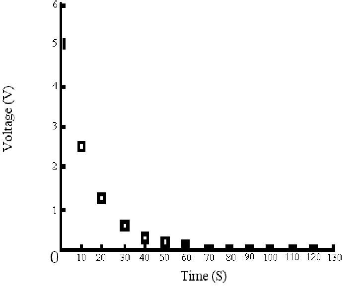
4: Graph of Voltage vs. Time for the charging phase of the 220m
F capacitor and the 56KW
resistor.
Diagram
4: Graph of Voltage vs. Time for the charging phase of the 220m
F capacitor and the 56KW
resistor.
![]() Answers
to Lab Questions
Answers
to Lab Questions
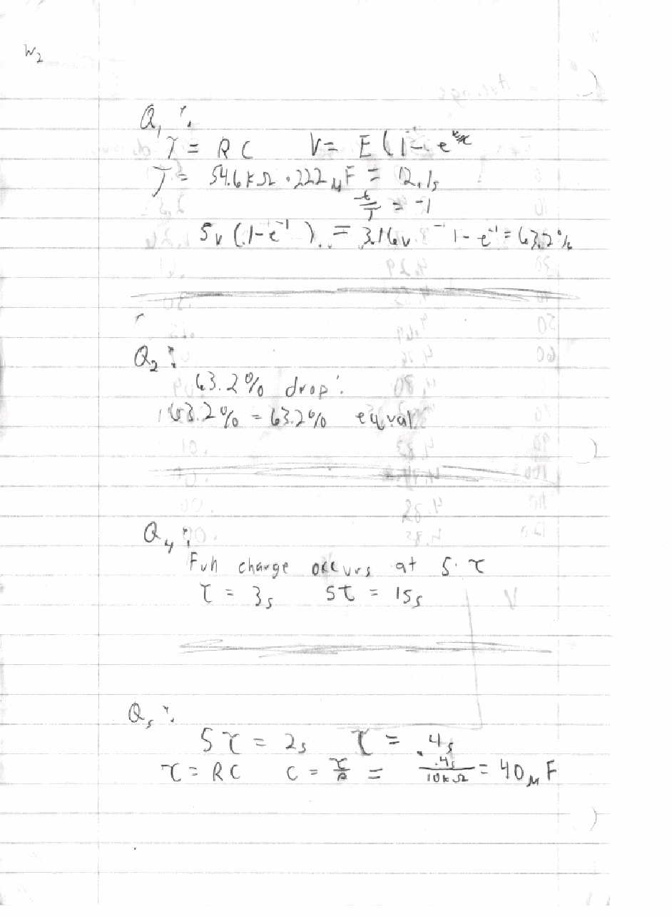
1) Q: What should the voltage be after 1 time constant and what percent of total power is it?
A: 3.16v which is 63.2% of the original power.
Work:
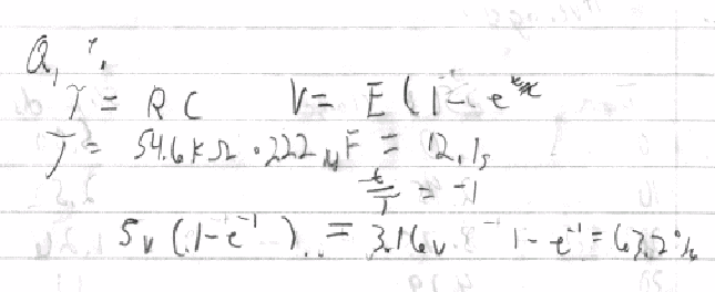
2) Q: Does the percent in Q1 agree with the given drop of 63.2%?
A: Yes, there is no difference between the two calculations.
Work:

3) Q: Was the plot of Voltage vs. Time for the discharging phase expected?
A: Yes. As the charge travels through the circuit, the voltage across the capacitor should drop and the graph shows that it does.
Work:
![]() No
work required
No
work required ![]()
4) Q: If a circuit has a t of 3s, how long will it take for it to become completely charged?
A: 15s
Work:

5) Q: What value of capacitor is required for it to be fully charged by a 10KW resistor in 2s?
A: 40mF
Work:

6) Q: What were the working and surge voltages of the capacitor used?
A: Working: 50v Surge: 500V
Work:
![]() No
work required
No
work required ![]()
7) Q: What is leakage current?
A: Leakage current is current that flows between the two plates of the capacitor through the separating.
Work:
![]() No
work required
No
work required ![]()
![]() Conclusions
Conclusions
From this lab one can prove that the increase of voltage across a capacitor as a function of time while it is charging can be explained mathematically as:
V = E * (1 - e ^ -t / t). Also, the discharge of a capacitor can be described as:
V = E * e ^ -t / t. We also define t as being the time constant which is R * C. We also discover that after a period of 5 * t, the capacitor is close enough to being fully charged or fully discharged to be able to mathematically described as being so.
![]() Attachments
Attachments
A) Copies of lab recordings
B) Copies of calculations
C) Original lab handout
