![]() Overview
Overview
EL - 250
Advanced Analog Circuits
Lab #5: Operational Amplifier Frequency Modulator
Andrew Buettner
![]() Overview
Overview
Operational amplifiers have many uses in the common world. They are a simple circuit that compares two voltages and gives the result of which is greater. One common use of these circuits is as a trigger oscillator. The waveform produced by an operational amplifier is a mix of a triangle wave and a square wave. Although this does not have any practical purpose in modern bandwidth regulated communication, these waveforms can be used to produce a type of modulation. This lab explores the concept of using an operational amplifier (op - amp) to produce frequency modulation.
![]() Objective
Objective
The objective of this lab is to use a 741 op - amp to produce a frequency modulated signal. Then to calculate the operational parameters of this modulator.
![]() Equipment Used
Equipment Used
1) Oscilloscope #1488
2) Multimeter #31101514
3) Trainer #1044
4) Function generator #1044
5) Various components from the EL - 250 Lab kit
![]() Procedure
Procedure
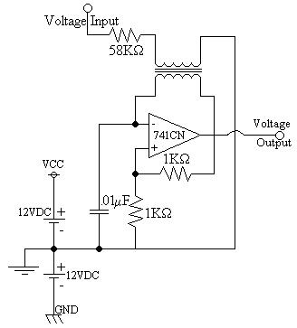
1) Assemble
the following circuit:
2) Power the trainer and observe the waveform produced by the circuit.
3) Calculate the frequency and peak voltage produced by the circuit.
4) Apply the modulation signal to the input and observe the waveform produced.
5) Calculate the modulating signal frequency and peak voltage.
6) Calculate the lowest and peak frequencies produced by the modulator.
![]() Data
Data
1) Diagram 1: Schematic 1, Enlarged view

2) Table 1: Component Data
|
|
Voltage: |
Frequency: |
|---|---|---|
|
Carrier: |
G3.6V |
17KHz |
|
Modulation: |
G5V |
1KHz |
3) Table 2: FM Waveform Data
|
|
Vm: |
Frequency: |
|---|---|---|
|
Lower: |
-5V |
14KHz |
|
Upper: |
+5V |
20KHz |
![]() Answers to Lab Questions
Answers to Lab Questions
1) Q: What is the resistive equivalent of the transformer with no modulation?
A: Rx = 852W
2) Q: What is the sensitivity of the modulator?
A: Kf = 600 Hz / V
3) Q: What is the peak deviation and modulation index of the FM modulator?
A: d = 3KHz / V, m = 3
4) Q: Using Bessel functions, what is the frequency spectrum of the modulator?
A: 11KHz, .04V; 12KHz, .14V; 13HKz, .47V, 14KHz, 1.12V; 15KHz, 1.76V; 16KHz, 1.22V; 17KHz, .94V; 18KHz, 1.22V; 19KHz, 1.76V; 20KHz, 1.12V; 21KHz, .47V; 22KHz, .14V; 23KHz, .04V.
5) Q: What are the resistive equivalents of the transformer at the peaks of the modulation?
A: RFL = 1.03KW, RFH = 724W
![]() Conclusions
Conclusions
This lab has demonstrated how to use an op - amp to produce a frequency modulated wave form. Although this FM wave form has little to no practical use in the actual world, it is a good way of demonstrating the basic operations of a FM transmitter. The circuit, to an extent, follows the basic rules and patterns of a FM modulator.
![]() Attachments
Attachments
Original lab data
Calculations