Objective
The objective of this lab is to construct an AM wave demodulator for the purpose of demodulation an AM wave.
Equipment Used
1) BK Precision Generator #3022#
2) Trainer #1055
3) Multimeter #1268
4) Oscilloscope #1864
4) Various components of the EL - 261 Lab Kit
Procedure
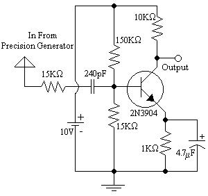
1) Assemble the Following Circuit:

2) Set the Precision Generator to the following settings:
a) Frequency = 100KHz
b) Frequency Control on
c) Sweep Time on
d) Sweep Width off
e) Modulation set to ¾ turn (2 o-clock position) clockwise
f) Function = sinewave
g) Duty - Counter clockwise - CAL.
h) TTL on
i) Offset - on - CCW
3) Adjust the generator amplitude to produce an amplitude of .3V peak - to - peak
4) Adjust the modulation control to maximize the modulation without distortion
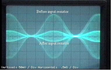
5) Show the resulting waveform before and after the input resistor
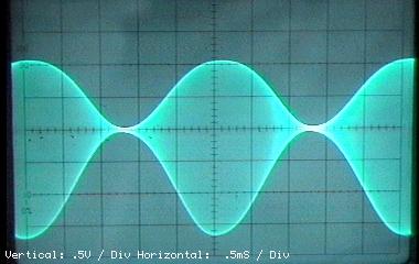
6) Show the wave produced at the collector
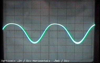
7) Connect a .03mF capacitor between the collector and ground and show the resulting waveform at the capacitor
8) Measure the voltage at the Emitter, Base, and Collector
Results
1) Diagram 1: Schematic 1 Enlarged View
2) Diagram 2: Waveform from Precision Generator
3) Diagram 3: Waveform from amplifier with no output capacitor
4) Diagram 4: Waveform from amplifier with output capacitor
5) Table 1: Voltages from amplifier
|
|
Emitter |
Base |
Collector |
|---|---|---|---|
|
Voltage (AVG): |
.215V |
.860V |
7.83V |
Answer to Lab Questions
1) Q: What is the modulation frequency used by the generator?
A: 2KHz
2) Q: What percentage modulation was used for the waveform?
A: m Z .935
3) Q: Which waveform indicates the production of two unequal envelopes?
A: The waveform produced at the output of the amplifier.
4) Q: What time constant was created with the use of the .03mF capacitor?
A: 1.88mS
5) Q: What is VBE?
A: .645V
6) Q: What was IE?
A: approximately .217mA
7) Q: Is this an example of a square law demodulator?
A: This circuit does not act as a square wave demodulator because the output is the result of the same signal being subtracted from it's self. i.e. 2(sin(wmt))sin(wct) - (sin(wmt)sin(wct) = (sin(wmt)sin(wct). Then put through a filter causing the output to be: sin(wmt)
Conclusions
From this lab it is concluded that a transistor biased in the non - linear portion of the VE - IE graph can be used to demodulate an AM waveform. I believe that this lab is very accurate and I believe that the results were exceptionally good. Also, the VBE was calculated to be .645V which is a difference of less than 8% from the expected BJT value of .7V This proves that the results were accurate.
Attachments